Each functional domain consists of one or more distinct network functions (NFs), which are depicted in Figure 1. Some of these NFs interconnect through named point-to-point reference points, which are realized as interfaces in the protocol design. This applies to both the user plane (UP) interfaces and all 5G radio access network (RAN) to 5G core (5GC) interfaces.
The 3GPP has defined the 5GC architecture using the principles of service-based architecture (SBA). In this model, the functionality of certain 5GC NFs is made available via an exposure interface, offering a set of services that can be accessed by other NFs, provided they are permitted to do so. The purpose of applying the SBA principle is to optimize cloud-based 5G implementations.
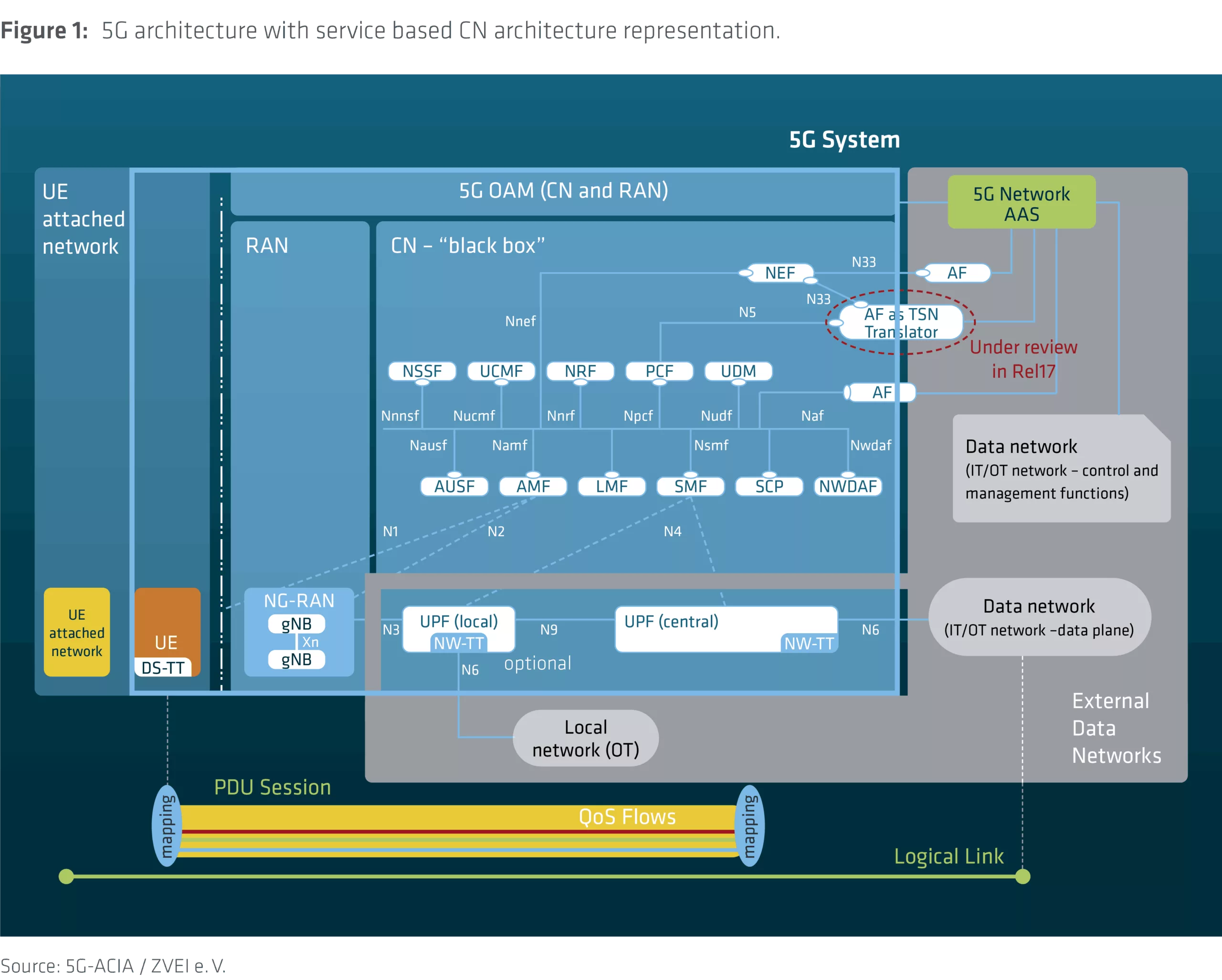
The NFs shown in Figure 1 are part of the 5G system and are described in [1]. Not all of them are required in every scenario. For instance, the location management function (LMF), time-sensitive networking (TSN) related functions, and network data analytics function (NWDAF) are part of the 5G system but may not necessarily be visible to the factory network or objects in flexible deployment scenarios.
A packet data unit (PDU) session provides end-to-end user plane connectivity between the user equipment (UE) and a specific data network (DN) through the user plane function (UPF). The UPF handles the user plane path of these PDU sessions, providing functions such as packet routing and forwarding, traffic steering, quality of service (QoS) handling, and uplink/downlink rate enforcement. The UPF is controlled by the session management function (SMF), which sets the QoS parameters for these sessions. To highlight the architecture principle of supporting access to both local and centralized services, Figure 1 shows two UPFs. A UE can establish multiple parallel PDU sessions to the same or different data networks (DNs). For more information on deployment with shared RAN and control plane, refer to the topic “5G NPN Deployment Options.”
The application function (AF) is designed to enable end users, such as factory operators, to add custom applications for accessing the functionalities of the 5G system. Support for network function virtualization (NFV), whether full or partial, is also a key design principle of the 5G system architecture. All NFs can be implemented as either physical network functions (PNFs) or virtual network functions (VNFs). A 5G system deployment can contain any combination of both PNFs and VNFs.
Figure 1 does not include details of the next generation radio access network (NG-RAN). It only presents the gNB (Next Generation Node B, i.e., 5G base station) and the reference point Xn, which is used to interconnect neighboring gNBs. As defined in [2], each gNB in an NG-RAN may be further divided into a central unit (CU), which is connected via the F1 interface to one or more distributed units (DUs).
[2] 3GPP Technical Specification 38.401, “NG-RAN; Architecture description”, v18.4.0, 12/2024,