Example case: An automated guided vehicle (AGV) communicates with its application server (control). The IP packet stream is transferred to the non-public (private) 5G network via the industrial 5G router connected to the AGV.
It is recommended to test the “wireless communication system” in different phases:
- Before the industrial application goes live: the industrial 5G router is tested in the lab (device testing in lab) and the network performance is tested after/during network deployment (network verification and acceptance in the field)
- If the network is operational and the application does not work properly, the root cause of issues needs to be investigated in the troubleshooting phase.

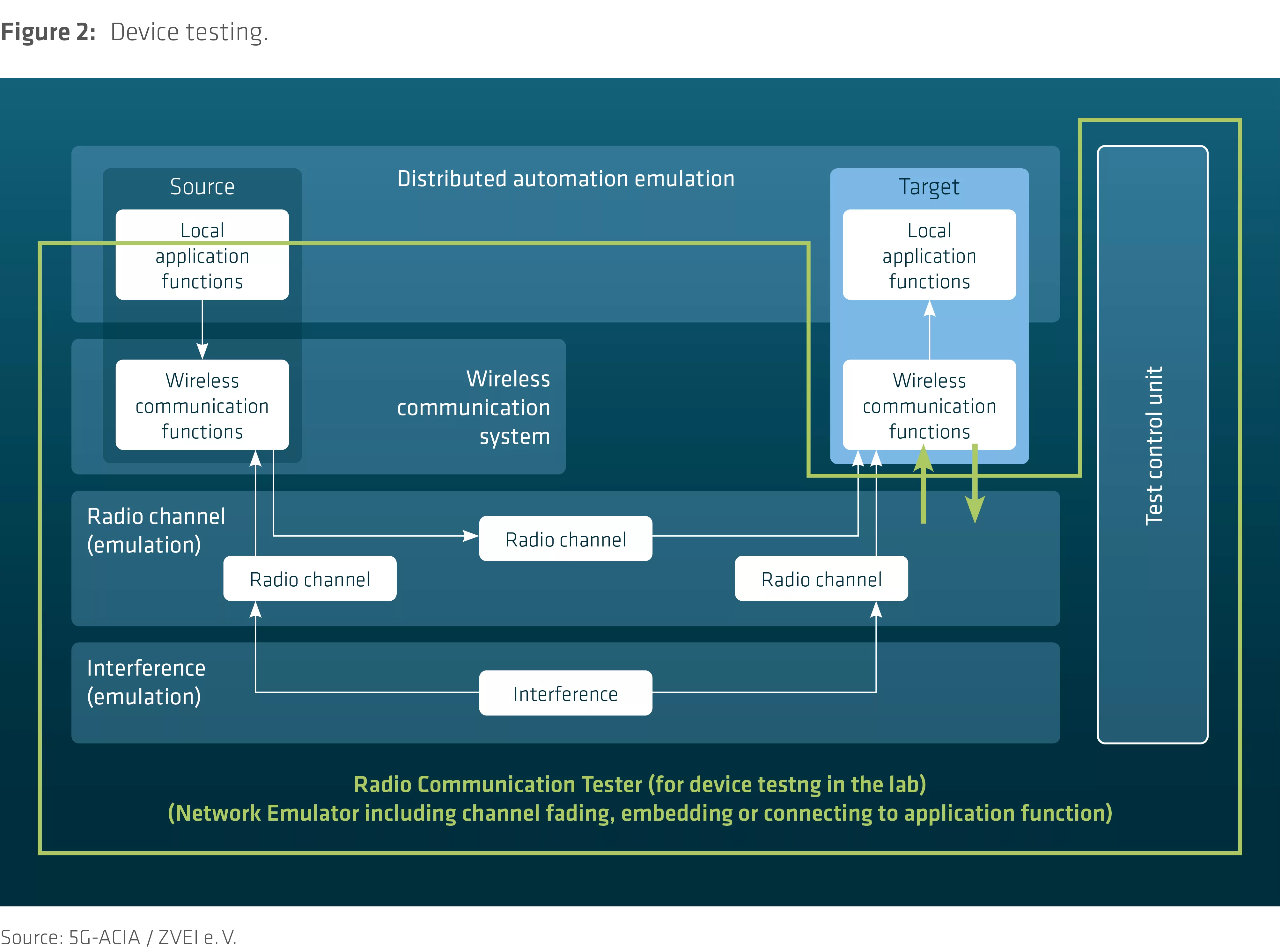
Industrial Device Testing in a Laboratory Environment
This is the traditional setup for testing cellular devices. A network with an RAN (including fading profiles), a core network, and data servers (or a connection to application servers) are emulated in a radio communication tester and the device behavior is tested under various conditions in the lab.
Industrial Network Performance Testing in the Field:
The following figure shows wireless communication system components, an industrial device and a non-public (private) network.
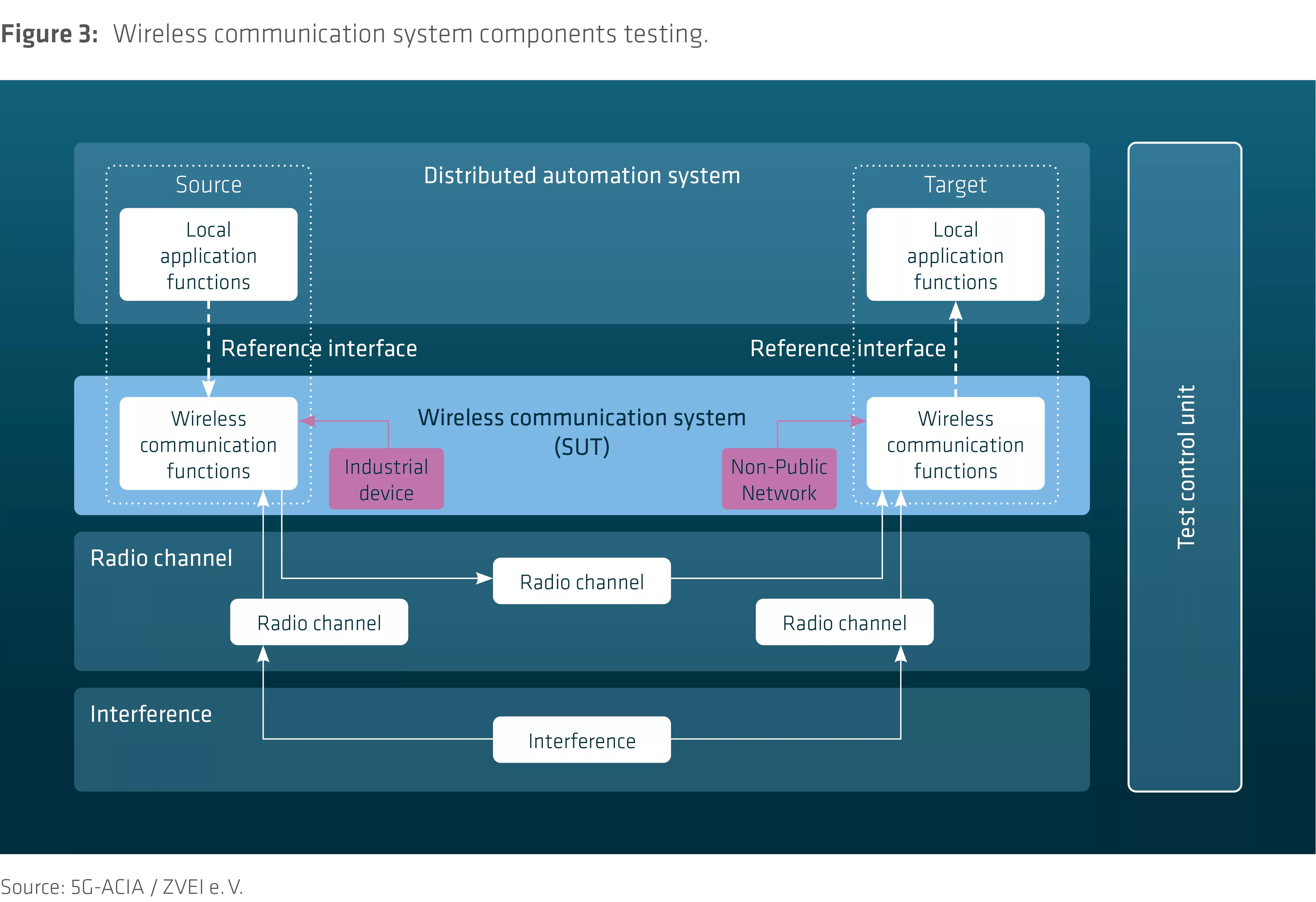
To test the private network’s performance, a test device emulates real use cases by sending packets that are reflected back.
The following figure shows how the signal flow of a real industrial use case can be emulated and the performance of the non-public (private) network tested.
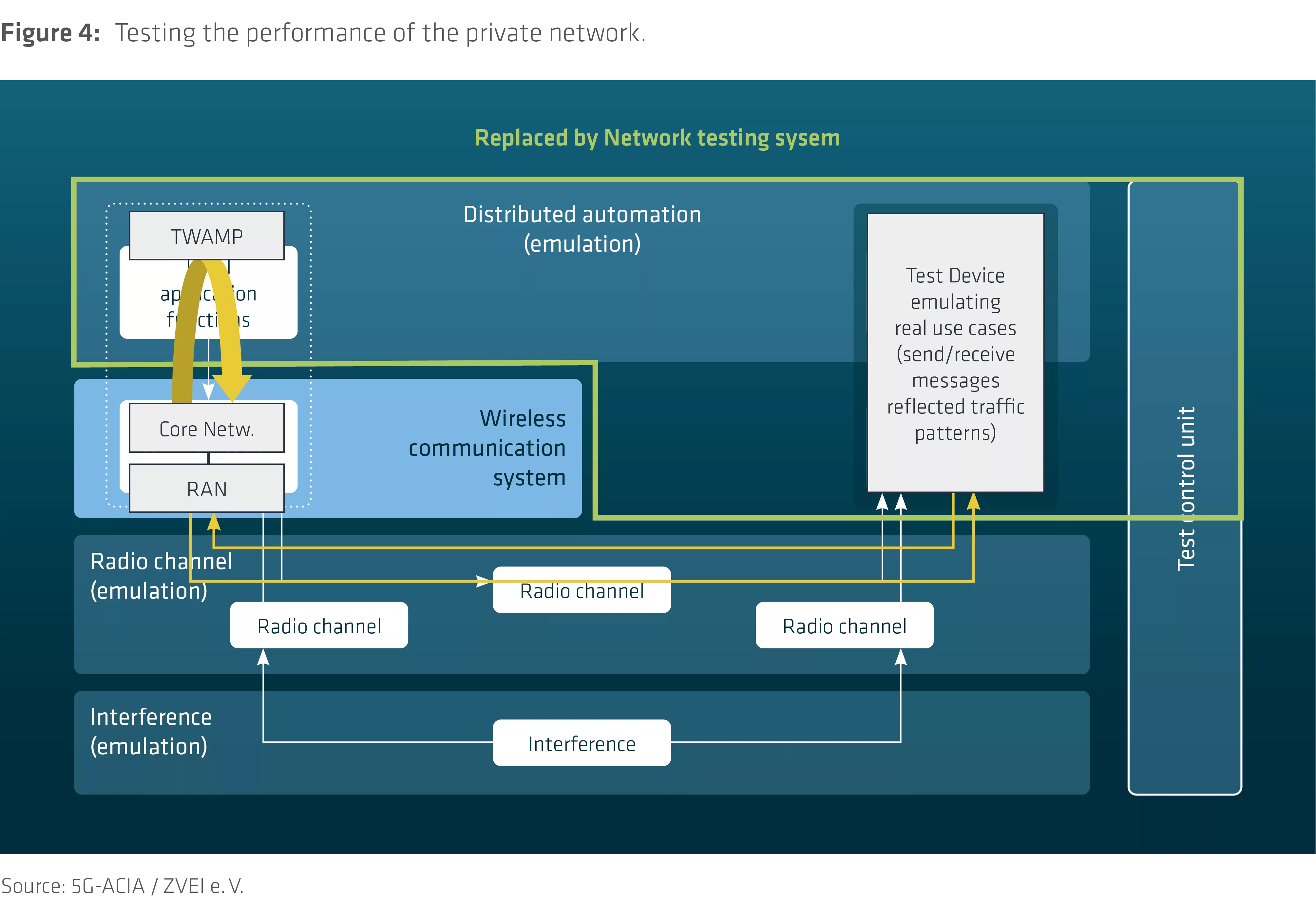
The measurement software in the test device emulates traffic patterns of various real industrial use cases in terms of transfer interval and message size and analyzes performance based on the application’s requirements.
The measurement hardware can be a measurement probe based on a 4G/5G industry module or a smartphone running measurement software.
The interactivity test (specified in ITU-T G.1051) can emulate traffic patterns of real applications (symmetric and asymmetric patterns). The emulated traffic (transfer interval, message size) sent in the UL direction by the test device is reflected by a TWAMP-enabled node and received by the same test device in the DL direction. The TWAMP server should be located close to the private network’s core network.
The expected results are a per-packet round-trip latency (= “response time” = UL + DL “transmission time” + TWAMP server processing time), the packet delay variation and statistics on the number of transmitted packets (10th percentile, median, 90th percentile), including long-term statistics over a huge number of packets to investigate service availability in terms of the number of nines (e.g. 99.999%).
The test elaborates the capability of the private network to serve a certain industrial use case with a dedicated traffic pattern and performance requirements. A variety of test cases emulating different industrial use cases can be configured in one test campaign and executed in a type of walk test throughout the whole area of the private network.

If an industrial device communicates with another device via the non-public (private) network, the same test method is applicable. Performance-wise there is no difference between whether one UE (the test device) gets the reflected data packets or the data is transferred via the RAN/Core to a second UE.